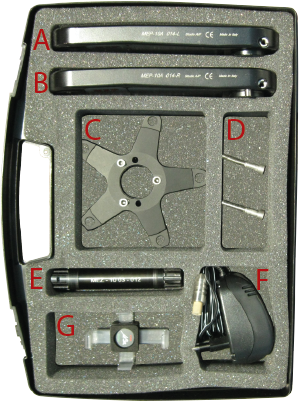
The MEP case (shown in figure) contains:
- #1 left crank arm
- #1 right crank arm
- #1 spider with
#3 M5x20 hex socket cap screws - #2 M6x40 hex socket cap screws
- #1 bottom bracket spindle
- #1 battery recharger
- #1 Patented Smart & Telephone holder
i) Right crank arm assembly on spider:
-
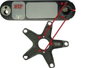 Match the 2 pins leaning out from the right crank arm with the two corresponding holes into the spider (see red lines)
Important:do not push nor press with excessive force. Plugging will be achieved in next step -
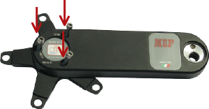 Insert the 3 M5 hex socket cap screws.
Screw and tighten them untill the M5 tighten torque value
ii) Right crank arm assembly on spindle:
-
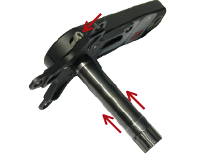 Connect the bottom bracket spindle via the one-way-fit spline into the splined hollow of right crank arm
Important:the bottom bracket spindle can be inserted in any direction, whereas the splined hollow allows for a unique phase, preventing mounting errors
 -
Insert one of the two M6 screws into the right crank arm.
Screw and tighten the screw untill the M6 tighten torque value
iii) Chainrings mounting (2 or 3 units) on spider arms:
-
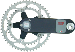 Precisely match chainrings and spider
- Screw tightly the specific 5 bolts to get a steady connection
iv) Spindle assembly in BB shell:
-
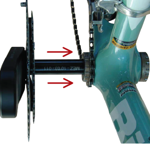 Insert the free end of the spindle into bottom bracket shell with external bearings
Important:Depending both on bottom bracket shell width (common values range from 68 to 73mm) and on cups width, it might be necessary to put some spacers along the spindle between crank arms and cups to avoid annoying axial clearance
v) Left crank arm assembly on spindle:
-
 Carefully catch and insert left crank arm into free side of the spindle leaning out bottom bracket shell
- Insert left crank arm until contact with the spindle
- Tighten the M6 screw untill the M6 tighten torque value to ensure crank arm-spindle assembly
